.png.279748a58a2b862b7aa5f3b84126e232.png)
Search the Community
Showing results for tags 'jay rose. -35dbu pad. diy attenuating cable. mark kirchner'.
Found 1 result
-
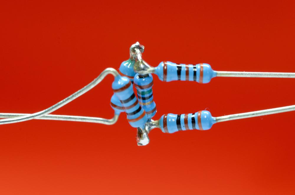
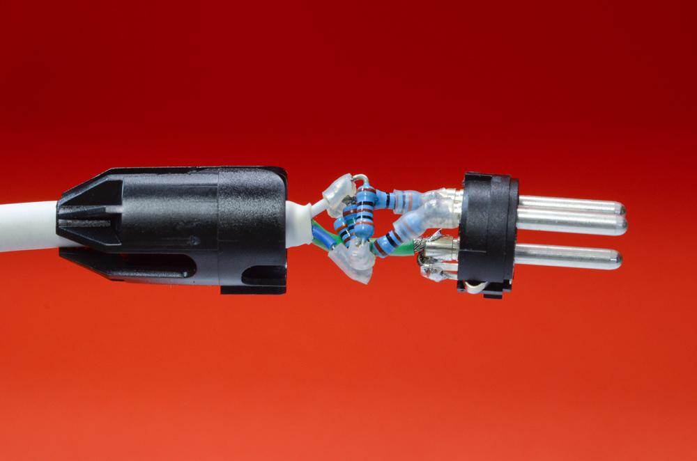
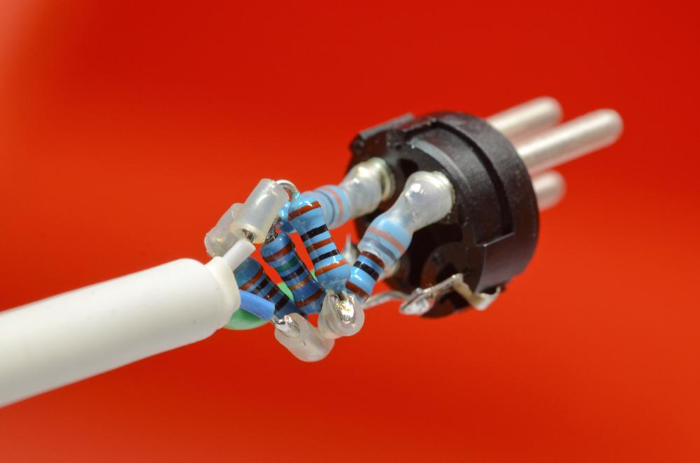
-35 dB ATTENUATION CABLE This project came directly from Jay Rose’s book Producing Great Sound for Film and Video, 3rd edition. On pages 179 to 181 Jay explains what resistors to use and diagrams three different circuits. I chose to make the “balanced output to balanced input” as a cable instead of building it into a XLRm to XLRf barrel. This attenuating circuit uses (4) – 301 Ohms 1/4 watt 1% film resistor and (1) – 15 Ohm 1/4 watt 1% film resistor. The challenge for me was figuring out how to get all 5 resistors soldered in the correct circuit design and still fit into a xlr connector. I have included 5 photographs that I made as I progressed, they uploaded out of order, tried to put them in order, no luck, I hope they are understandable. Thank you Jay for all your books. 1. Resistor "web" 2. Finished (side view) 3. Finished (end view) 4. Connecting to pin 2 and pin 3 5. 15 Ohm Resistor has the green band