Janik Hampe
-
Posts
35 -
Joined
-
Last visited
-
Days Won
1
Content Type
Forums
Gallery
Store
Everything posted by Janik Hampe
-
Since I am getting lots of requests for the files but have no time for the project at the moment I decided to release the files als CC0 / public domain. You can do with it whatever you want, modify, share, use commercially, anything. Have fun! You´ll find the .stl files and some explanations here: https://www.thingiverse.com/thing:4684864 I´d like to see your results and read from your experiences. Janik blimp-v2-no-supports.stl blimp-v2-minimal-supports.stl

-
Glad you like it. 🙂 There are lots of flexible filaments for 3D printing. And there´s also polypropylene available though I don´t think it´s very flexible. Many of the flexibles are based on TPU with some additions and vary from quite stiff to super flexible. The more flexible your filament is when not printed yet, the more tricky the printing process gets. Soft filament tends to jam right before going into the hot printing nozzle and needs really good low friction guidance inside the printhead. In consumer 3D printing there are basically two types of extruders: direct drive and bowden drive. Bowden drive uses a (bowden) tube from the extrusion motor pushing the filament to guide it to the heating element. Therefore you have some loss in precision when you push and pull something that is flexible. Direct drive on the other hand (and my printer is a direct drive one) have the extrusion motor right above the heating element, minimizing the lenght of potential filament stretching. Disadvantages of direct drive extruders are for example the added weight on the printhead which limits maximum print speeds. Coming back to your question: can one print a blimp using flexibles? I guess you could. You would have to print ultra slowly (I´m guessing 5mm/s instead of my current 40mm/s). And more importantly the filament mustn´t be too flexible. Its thin structure has to withstand the windjammer´s weight and securely clamp to the microphone. And finally the last problem: flexible filaments next to nylons, PETG and other advanced filaments are highly hygroscopic, soaking up humidity from the air and becoming useless that way. So a sealed drybox full of silica gel which you directly print out of is probably a must. That´s the main reason why I´m using simple PLA so far.
-
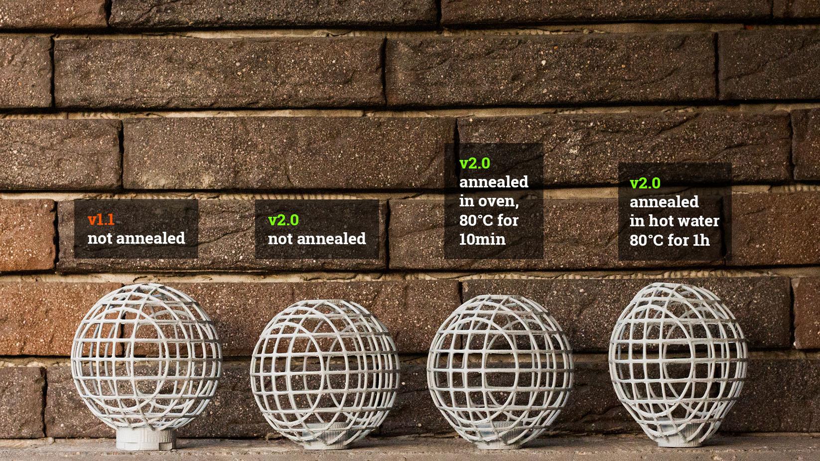
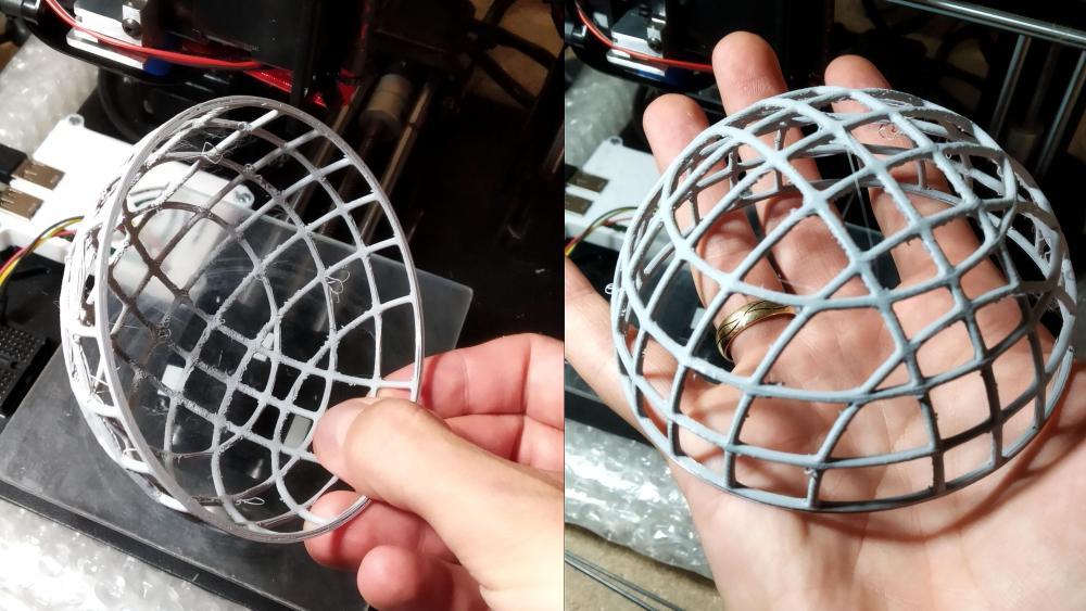
heat treatment / annealing I already talked about the low temperature resistance of PLA, my current material of choice. When you search for methods to make PLA stronger, you read a lot about annealing. You anneal a piece of 3D printed plastic by uniformly heating it up just above its “glass transition temperature”, let it crystalize (which it does on its own) and then slowly let it cool down. Now your piece of 3D printed plastic should be stronger, less brittle and able to resist higher temperatures. Perfect for leaving the blimp in the car during a hot summer. In the comparison picture above you can see that the annealed test parts shrunk in X and Z (width) but grew in Y direction (height). This is a common and well known property of annealed PLA and originates in the layers beeing added in Y direction. There are filaments like Proto-Pasta´s High-Temperature-PLA (HTPLA) which claim to have minimal shrinkage / growth and which I might try out. While not having HTPLA around my approach is quite simple. I do measurements of the part before annealing. Then I´ll anneal it and measure again. The factor of shrinkage / growth now can be factored in on the next print resulting in - hopefully - a part that shrinks into the correct dimensions. Which is more critical to the grooves which the o-rings sit in than to any other part of the frame. Getting correct dimensions on there after annealing is essential to securely grip the microphone. And we´re talking 0.1mm precision here. Test #1 I´m still trying to find the best, uniform annealing workflow. Because I didn´t want to use the oven from our kitchen, the first annealing process was done in a small pizza oven which on the lowest setting has 100°C. Because it also lacks convection heating I simply heated up the oven for 20 minutes, turned it of, let it cool down to 80°C, then placed the part inside and let it cool down. Repeated the whole process three times. Test #2 The second time, I used big pot full of water on an induction cooking plate which is temperature controllable to 60°C and 80°C. I simply left the piece too long in the hot water, resulting in a warped piece. I´ll continue optimizing this process and will post the results. To be continued...

-
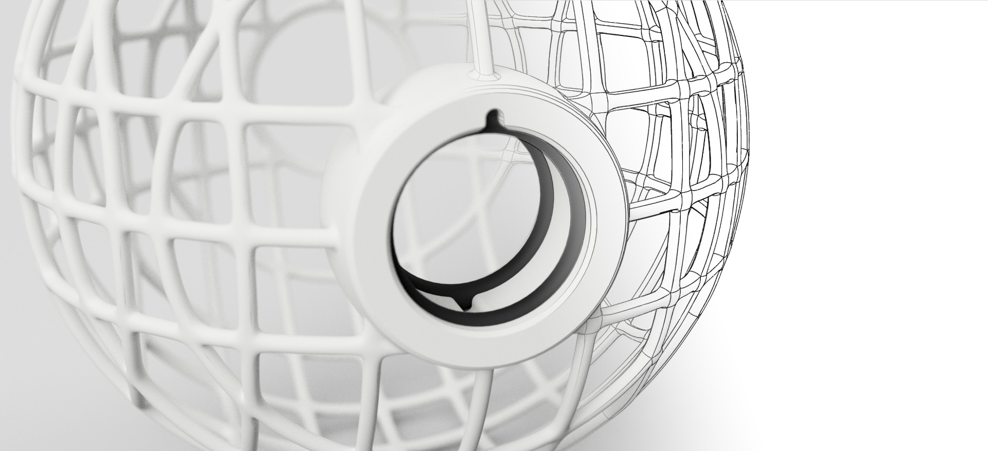
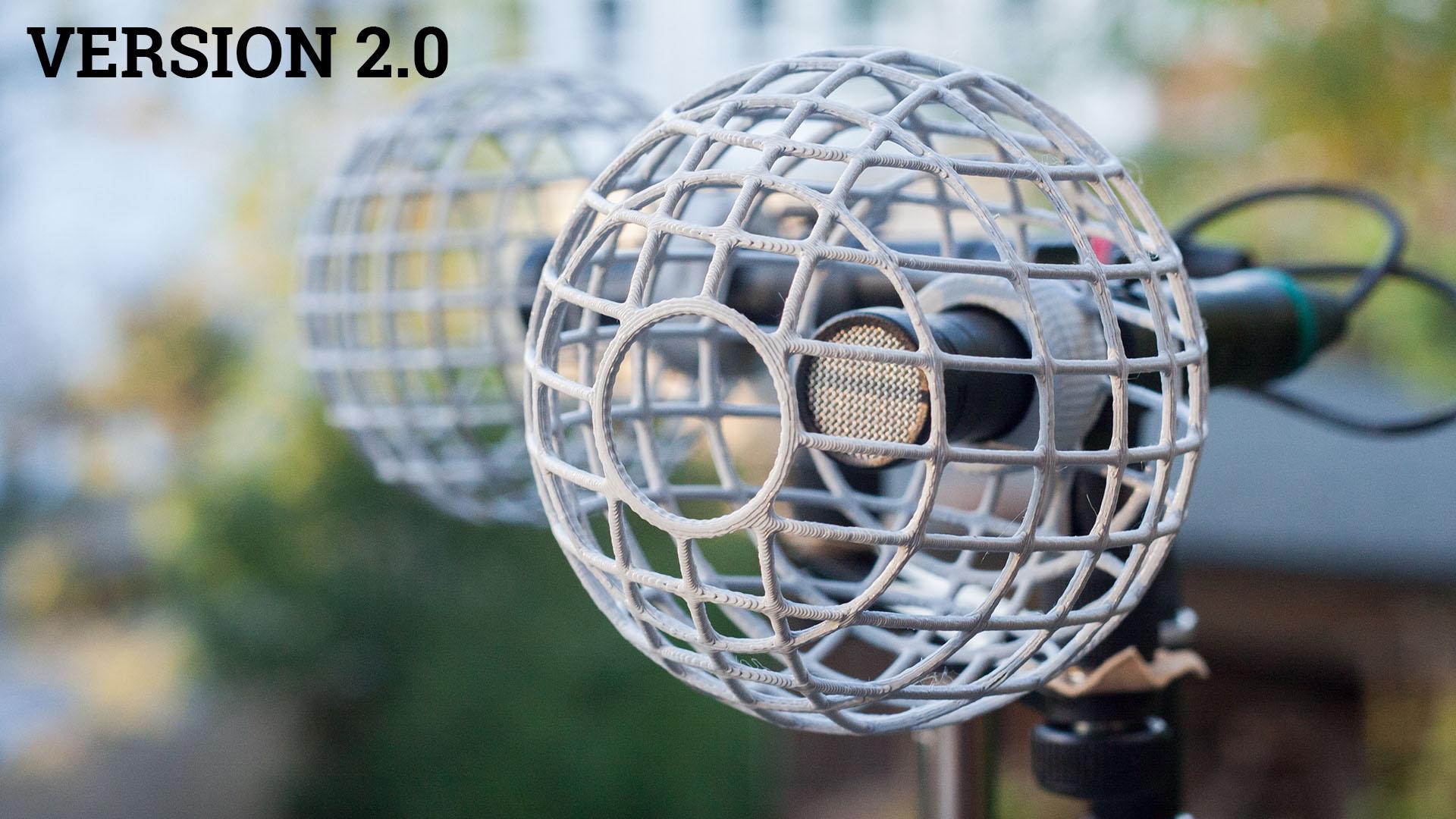
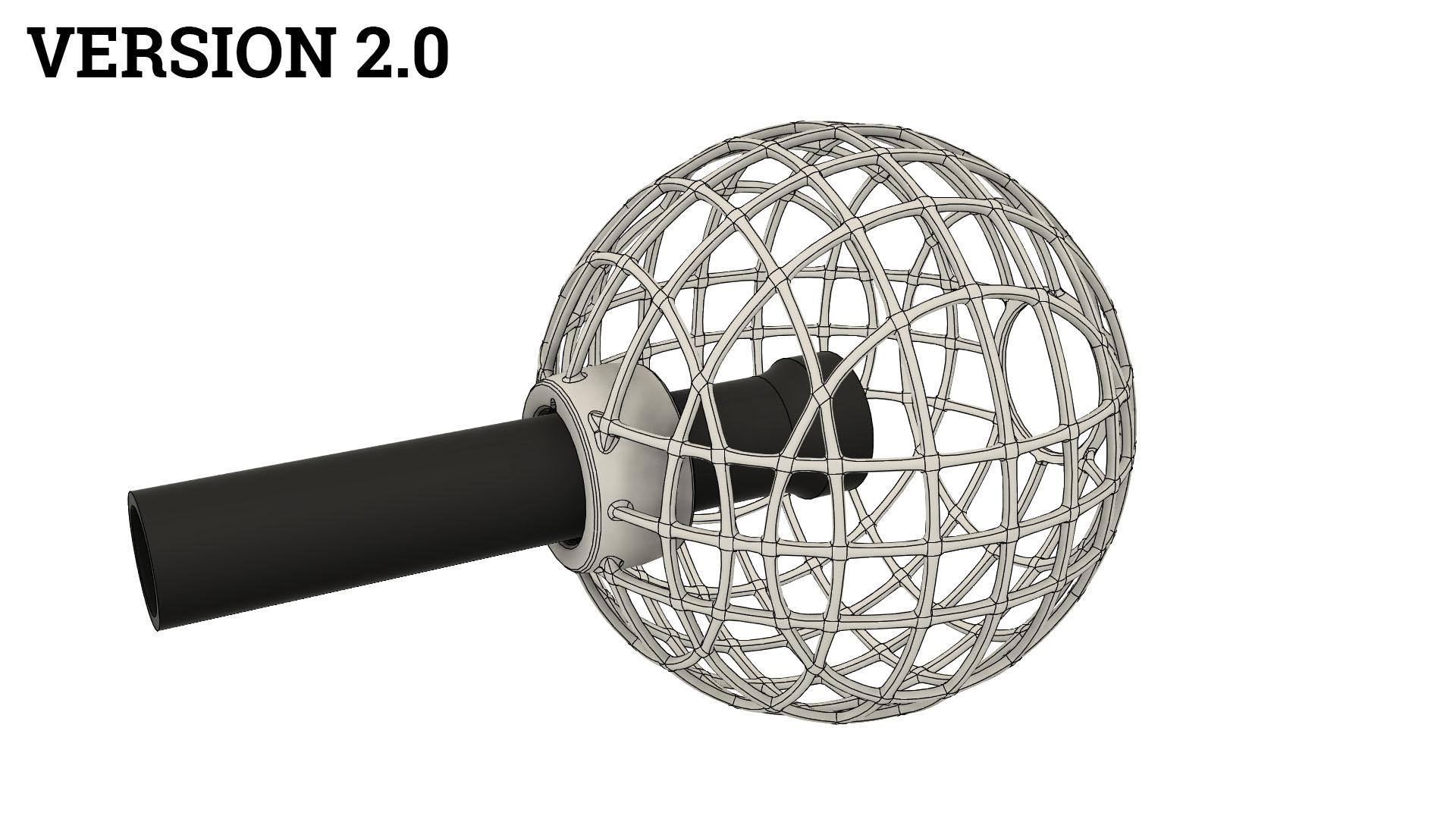
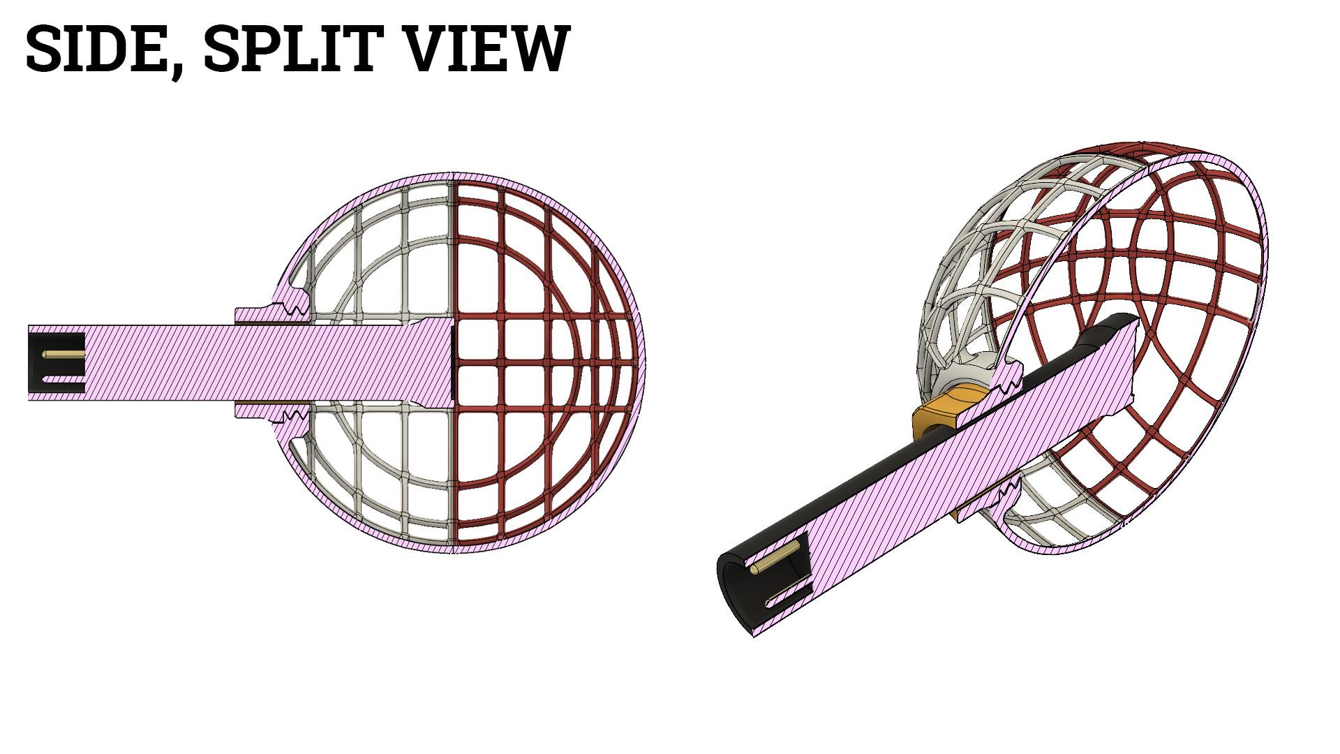
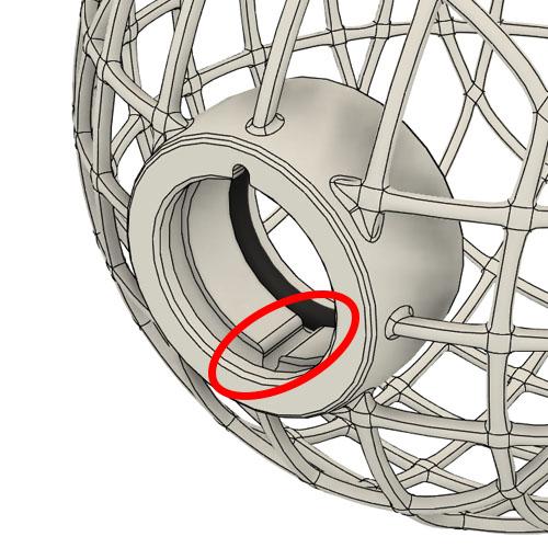
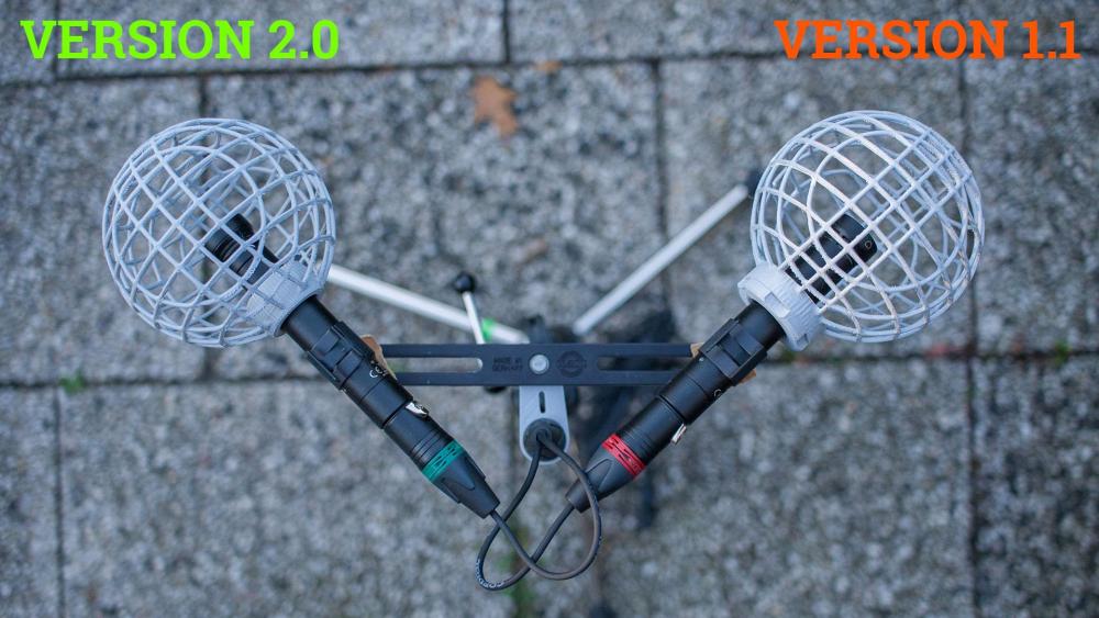
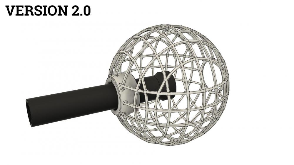
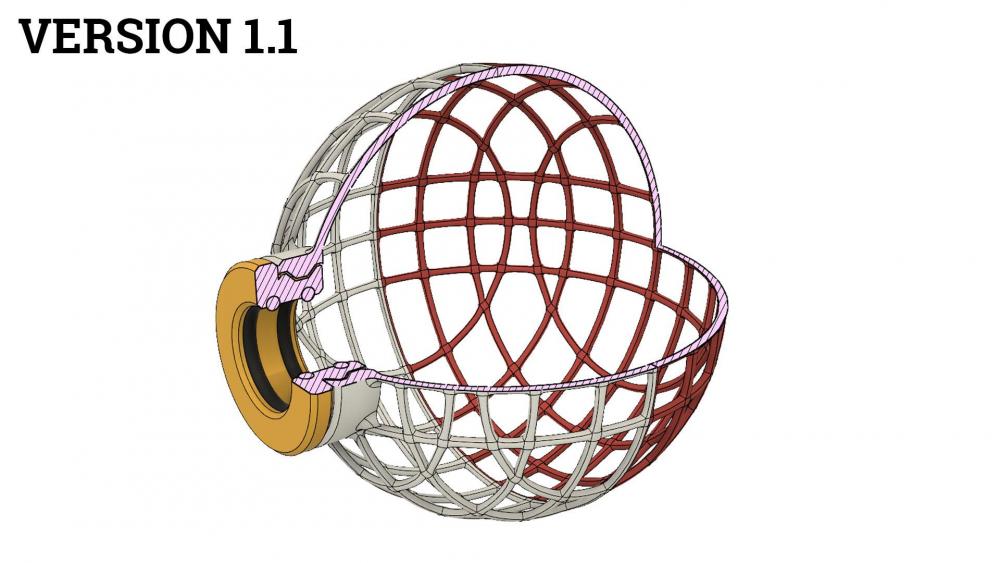
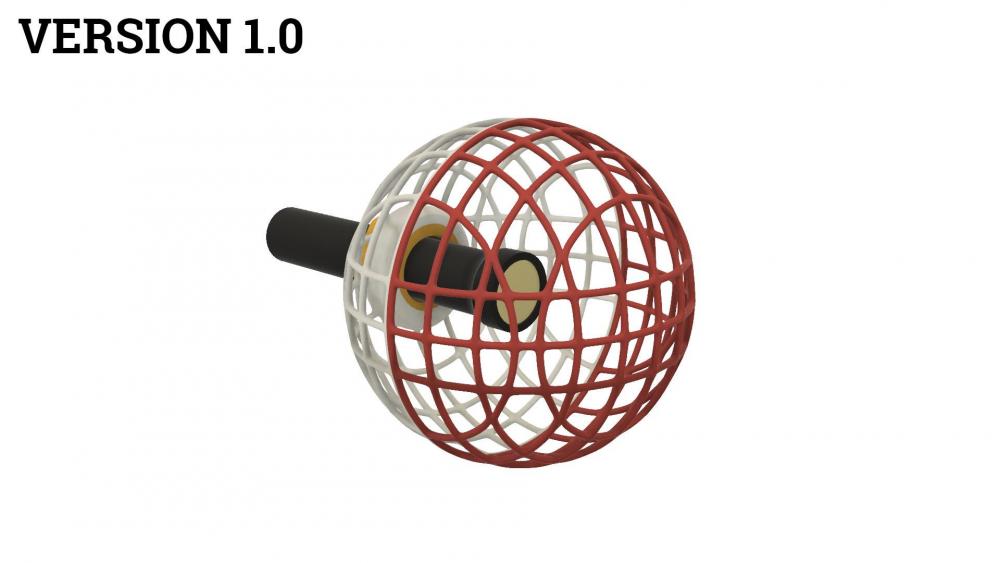
Inspired by the russian video posted here about DIY blimps I designed a frame with two openings. One bigger opening through which the whole microphone can be inserted and a smaller one which still holds the two rubber o-rings and clamps onto the mic. I do like version 2.0 very much. Having only one 3D printed part is a way more elegant design than having to thread two parts together. On version 1.1 the thread sometimes came loose when I had the windjammers on and it had to be tightened again. In my usecase, which is keeping the microphones almost always inside the blimps, this version 2.0 really does the trick. Here´s a comparison shot of version 2.0 and 1.1 from above. Also there has been a minor improvement. Because the frame is one solid structure now, the inner o-ring is less accessible. I wasn´t able to remove and recycle it from protoypes that were not longer needed. So I added one additional groove connecting the grooves which the o-rings sit in. This way, both o-rings can be accessed and removed from the outside using a paperclip. Coming up next: experiments in heat treatment / annealing ...


-
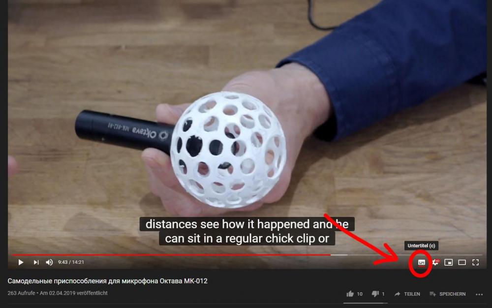
Wow, this one contains lots of great concepts, thanks for the hint! I especially like the idea of having two openings for passing the microphone through the frame. It´s shown at 9min 23s ( https://www.youtube.com/watch?v=nOOGusih2Eg&feature=youtu.be&t=9m23s ). I might try out that approach as it reduces the printed parts to only one. And you actually can activate automatically translated subtitles in the youtube player. The quality of translation is kind of bad but you´ll understand most of it.
-
Hm, nice thought. I could imagine some cleverly bent spring steel to work for this. And the halves would need to overlap in some way to avoid any side movement. Good Idea, thanks!
-
I´ll get some Lycra and test out, how flexible it is. Of course I´ll avoid any glueing or stitching if possible. I´ll also look up UV curing adhesives and keep them in mind. Well, that´s quite an engineering problem when using 3d printing as manufacturing method. Until now I haven´t been able to design such a mechanism that is reliable, rattle free and doesn´t use lots of material (affecting the sound) at the same time. Hi Allen, I have two rolls of PETG here but I´ve never been able to produce quality prints with it. Because of it´s hygroscopic nature, it soakes up lots of humidity from the air. When I was trying it out, it produced bubbly, soft and mushy, almoast foam-like prints that were stupid easy to bend. I suppose it´s the humidity. Or could it be something else? Do you experience similar behaviour? And do you de-humidify your PETG before printing? I´m thinking about getting a food dehydrator for this.
-
Oh, I´d absolutely love beeing able to produce a large surround rig with four or five channels. Or at least a stereo blimp. Although I´d probably need a larger 3D printer as my printing volume already gets maxed out with this project. For those of you who are into 3d printing: I plan on buying a Prusa i3 MK3s or above in the distant future. I also do experiment with 3d printed suspensions, but there´s nothing worth showing yet. For a multi channel blimp, I´ll probably prefer having custom suspensions inside for a more economical and efficent use of space. The blimp really shouldn´t be larger than it has to be to deliver good wind protection. And a key engineering aspect would also be a 3d printable, rattle free and robust locking mechanism to open up the blimp. This is a very difficult one. But let´s put all this into perspective. I´m going to finish this project here. Then I´ll test it intensively throughout winter and next year´s summer with huge differences in temperature, having it inside my car and using it on some of my shoots. PLA isn´t quite a UV resistant material and has a low glass transition temperature. At this temperature it gets soft and can deform when applying force. I´ll probably also try to produce some versions using ABS and test them too. Or nylon which is extremely difficult to print but also extremely tough. And I expect to learn lots of things through these tests. After all this, maybe, I´ll consider some bigger projects using what I learned from all this. We´ll see.
-
Hm, interesting. Not beeing a sailor and never having used a Nagra before I simply learned it the other way round. I have a background as a musician, used a lot of cables with red beeing the right channel and assumed this was an universal rule in color coding language. Well, the more you know... 😉
-
Hi Jez, could you explain what you mean by that? I really don´t get it. If you´re talking about the cables´ color coding, that´s red for "right channel" and green for "left channel".
-
As glueing Lycra to the inside of the frame becomes possible again, can you recommend any kind of glue for this job? The requirement is that the curing time has to be long enough to apply it to the whole inside of the frame part, get the Lycra into position and pressing it in evenly.
-
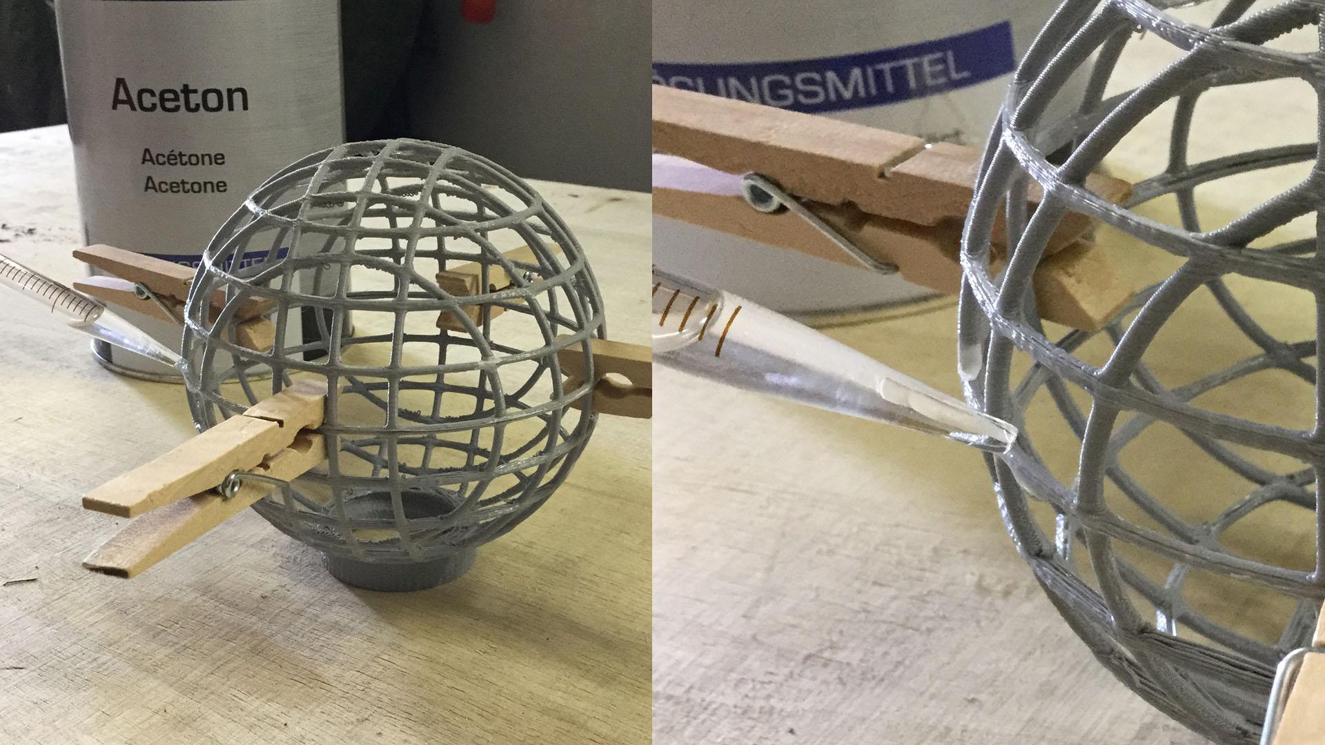
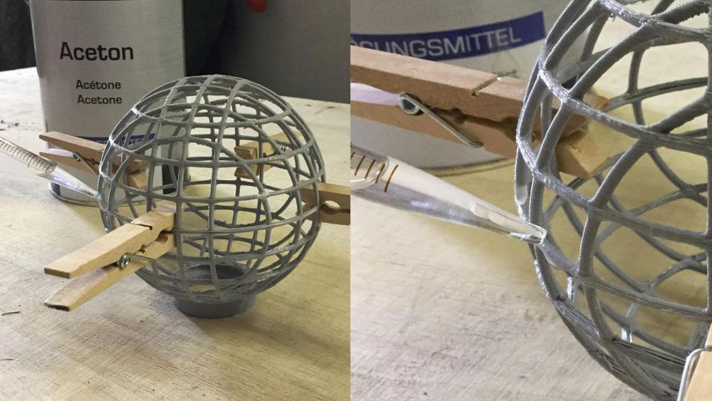
I haven´t. Instead I gave the acetone another shot. But this time I sanded the surfaces of the two frame parts with 100 grit sandpaper and after that with 180 grit. I purposely left the sanding dust on the parts to act as a filler for the still existing gaps. Clamped the two parts together and applied acetone with the pipette. And voilà - we have a really robust connection that set in like 30 seconds! I threw it on the ground with force several times and it didn´t break apart. So I finally have a solution for this problem! To be continued...
-
Really good idea and execution for quickly rigging a car scene. I´d probably put some heavy sand into the tube to prevent it from hopping around on bumpy roads. Thanks for sharing!
-
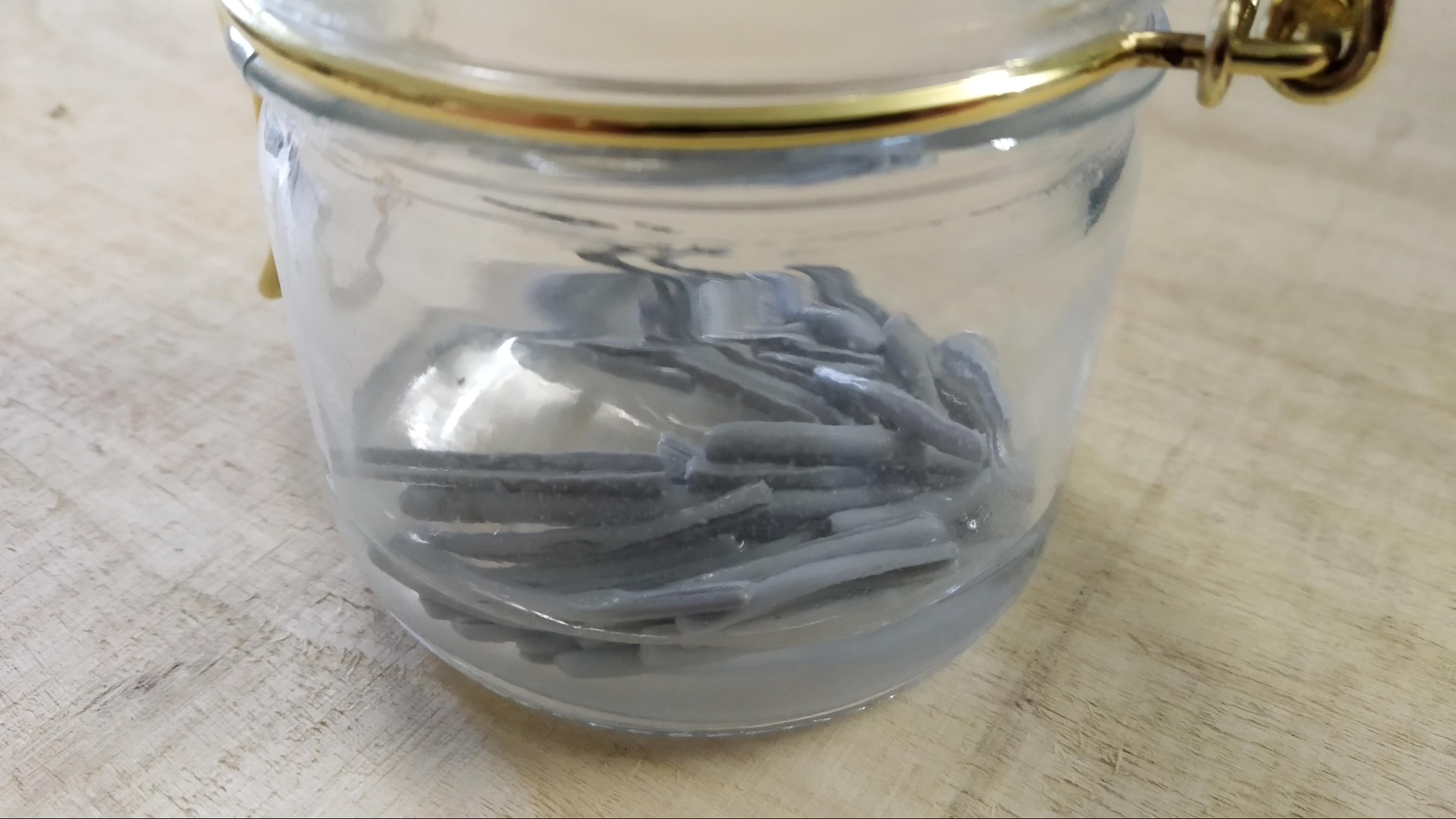
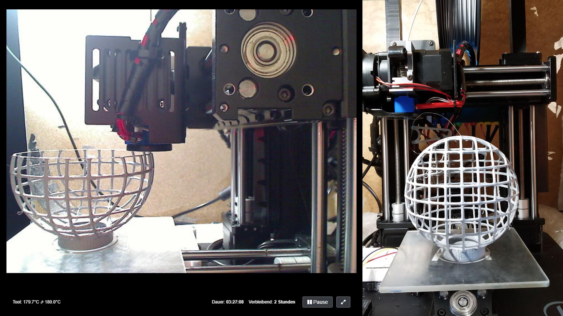
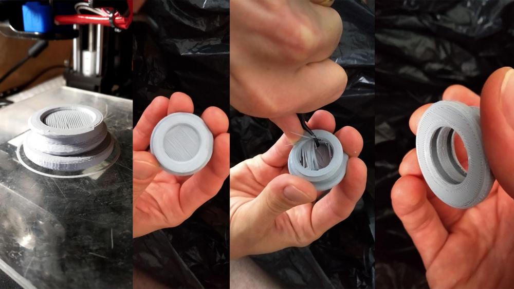
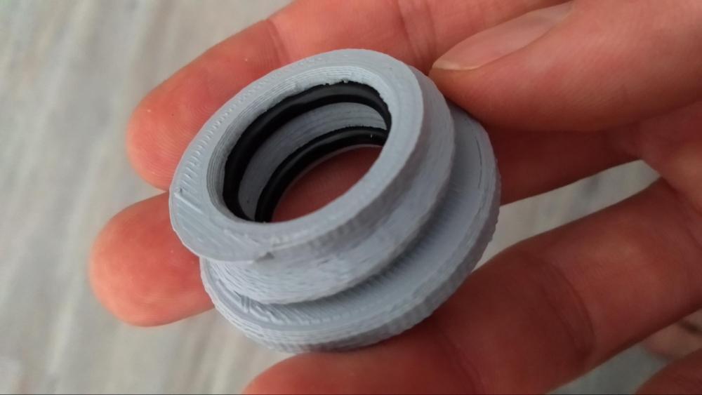
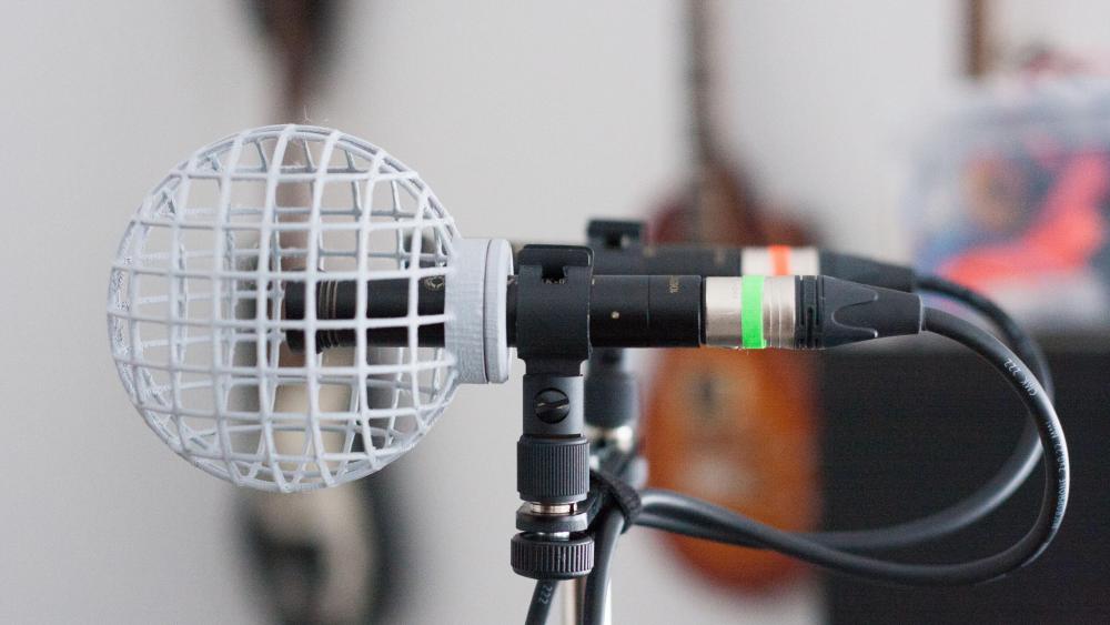
O-ring installation Here you see the new o-ring containing part. The technique used here is called “bridging”, uses thin support structures and enables printing over air and steep overhangs. The support layer beeing only 0.2mm thick is easily removed with a deburring tool or a knife. For print settings I doubled the layer thickness from 0.1mm to 0.2mm for faster prototyping. It actually improved the quality as stringing became less of a problem. ... and the finished part with o-rings installed: Adventures of solvent welding Finally, the welding of the frame. At first I tried to use pure MEK, brushed on the two surfaces and held them together. The result was disappointing. At some points the parts welded but the connection was weak and I was able to break them apart easily. MEK has a low viscosity like water and the surfaces of the print aren´t flat because of the 3D printed lines have lots of air space between them. I tried to dissolve some PLA in the MEK to get a higher viscosity slurry with a chance of getting more contact area. After hours of the PLA sitting in the MEK, it looked like this. No dissolving of the PLA, only the grey color pigments gets extracted. So back to the drawing board. I did more research. Some people seem to have success welding PLA with Tetrahydrofuran. Some were successful with Acetone (which I also tested and which didn´t work). The differences of ingredients of available printing filaments seem to be quite large so there´s no guarantee for success. Another option would be to print in ABS. ABS is a less brittle, more UV resistant material and can be welded simply with acetone. It requires higher printing temperatures, a heated or at least enclosed print chamber and a really (!) well bonded first layer. Otherwise it will warp from the build platform and the print will fail most of the time. Maybe i´ll concider it for future experiments, but not for now. The all-in-one approach Stepping away from all these chemicals I simply printed the whole frame all in one. I guess I never considered it before because I thought it was impossible due to the very steep overhangs. But I seem to have dialed in my settings for PLA quite well and it turned out very nice. The only disadvantage of this approach is that you can´t glue anything to the inside of the frame anymore. The whole thing now looks like this. I´m quite happy how it turned out so far. To be continued....


-
I asked the Sound Devices support about the possibility of a firmware upgrade bringing the usb auto copy feature from the 2nd generation to the MixPre-6 (1st generation). Sadly I was told, that the recoder does not have the capable hardware to perform this feature.
-
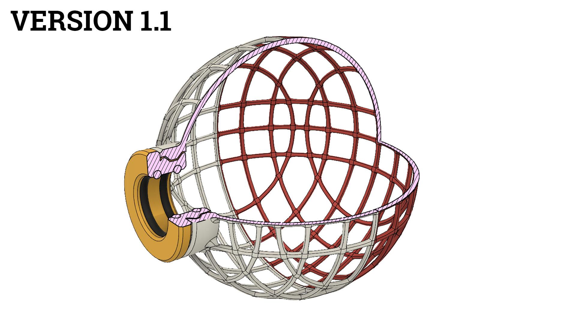
Chemicals and tool prep After reading a little bit about Dichloromethane, its extreme toxicity for humen and the enviroment I decided not to try it out. Instead I ordered 200ml Methyl Ethyl Ketone (short MEK) from Ebay. It turned out that none of my rubber gloves weren´t save enough for working with MEK as it dissolves quite a lot of plastics. So I ordered some quite expensive, thick and robust butyl gloves as well as a glass pipette. Version 1.1 Meanwhile I had developed the 3D model to version 1.1. The major changes are: Added two rubber o-rings as a rattle-free and slip-free interface layer between the 3D printed part and the microphone. Replaced the thread with a custom profiled thread which has been optimised to be 3D printed (no overhangs above 45 degree). Moved the internal thread from the inside of the frame to the outside. This uses up a little more space on the microphone but enables me to reduce the needed support structures to a minimum resulting in faster prototyping. The model now looks like this (support structures not shown): To be continued...


-
Wow, thanks Bernie for that very valuable piece of information. I´ll keep it in mind.
-
Hi Dalton, thanks for the offer. I´m glad you´re interested. But I won´t print two and send them over to you since it would be kinda expensive from germany and this is early prototyping stage. So there probably will be major changes until the final design. But I plan on publishing the files when this project is done so by then you might be able to have it printed locally at your area. Thanks! The material inside my original Rycote blimp actually feels like I imagine air filter to feel like, beeing quite stiff and therefore probably harder to process. Of course it would be nice to use the blimps without fur. But my DIY projects often times suffer from me beeing too much of a perfectionist so there is no progress. For this one I decided to get things done. If the windjammers works, I´ll be using blimp + windjammer outside and foam inside. Simple as that. I´ll keep documenting my progress, stay tuned. Since I work on this between my jobs it only might take a while.
-
Variable limiters, great! The other features are only nice to have, but not essential in my opinion. Now I´m really hoping for a copy-to-usb-drive update for my first generation MixPre-6 as the argument of differenciation beween the models isn´t true anymore. Do we know any prices yet? Couldn´t find any.
-
Hi Mike, I plan on simply using Rycote Windjammers made for the Baby Ball Gag. They have some silky material on the inside to diffuse the wind that passes the fur. If that´s not enough, I´ll try to glue some nylon pantyhose material to the frame - either on the outside by by pulling it over or on the inside by inflating a ballon and evenly pressing it against the frame. This is also a reason why I split the frame by two. Having two halves probably makes this process easier. But that´s just brainstorming at the moment. What´s your guess on this? Will I need some additional material to cover the frame when I´m using Windjammers?
-
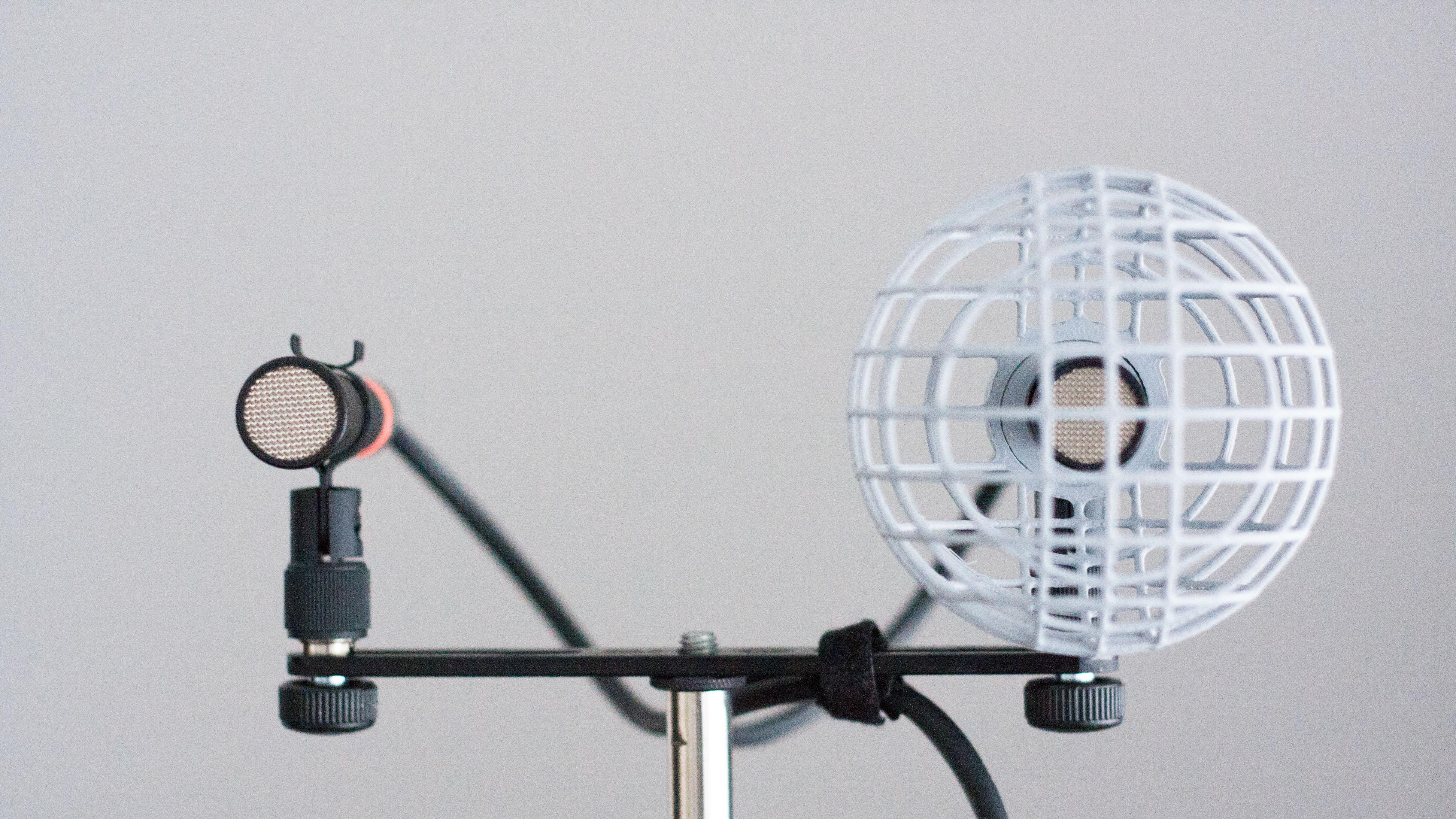
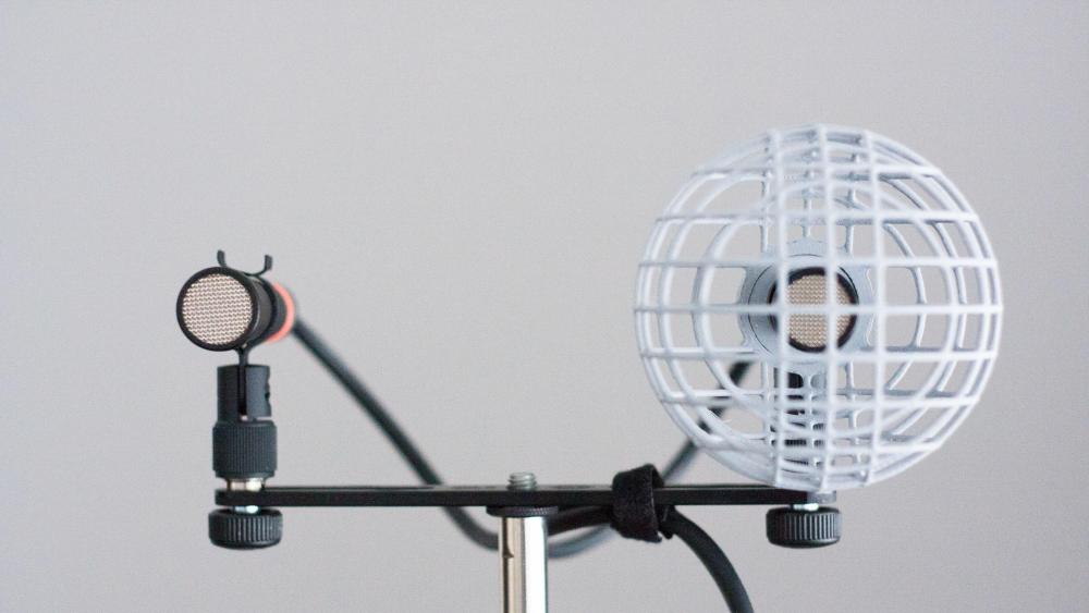
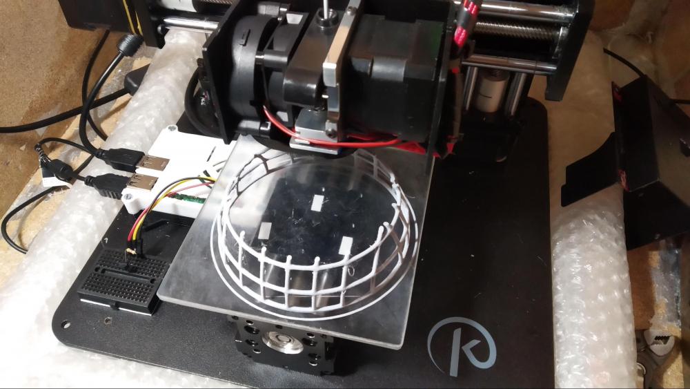
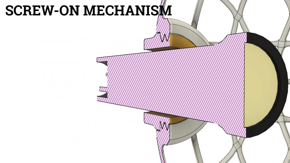
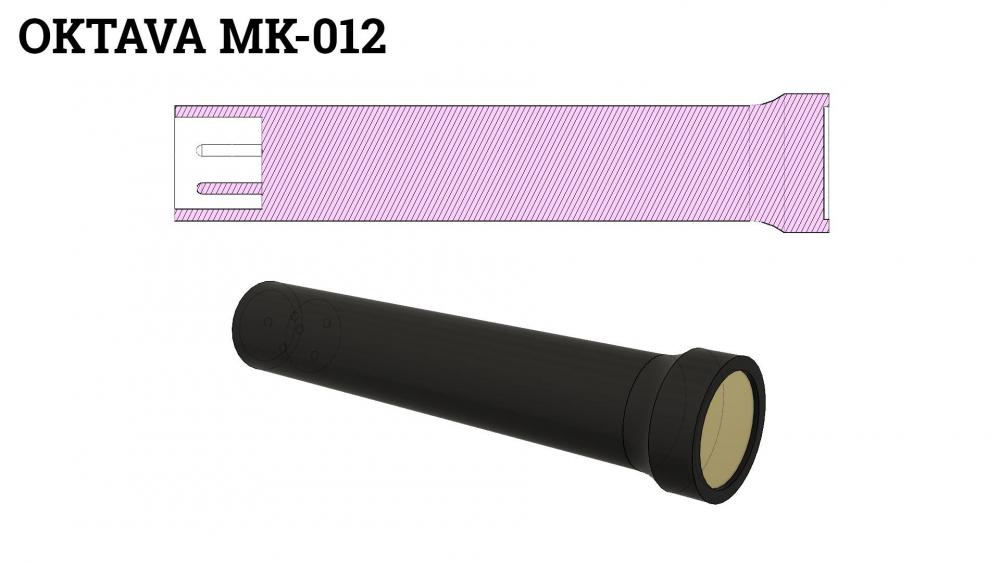
Hi everybody, I started a new DIY project. Since I really enjoy this forum and the wisdom shared I´d like to give something back. Here I´ll share the progress of this project with you. The situation I have a matched pair of Oktava MK-012 with cardioid capsules and use them for AB / ORTF stereo field recordings. I´d like to have good wind protection for them. Because I own a 3D printer and like to design functional parts I chose to give this approach a try before buying Rycote Baby Ball Gags or something similar. If everything works out I plan on buying just the fur from Rycote. For software I used Fusion 360 and Cura which both are free for non-commercial use. The 3D model I began with modeling the Oktava MK-012 to have a reference. This was pretty easy by just taking measurements and entering them into Fusion 360. Because the capsule´s diameter is bigger than the rest of the microphone´s body I had to come up with some technique to open up the blimp for mounting and unmounting. Rycote´s twist-to-lock mechanism is great but hard to model and close to impossible to 3D print for several reasons. Moreover that I refused to have the blimp split in the middle because of the increased amount of the mechanism´s material beeing right next to the capsule and probably affecting the sound. My solution to this problem was a screw-on mechanism with 3D printed threads in the back of the blimp. I already printed threads as small as M4 so these bigger threads shouldn´t be a problem. So there´s one small part with outer threads which stays on the microphone and there´s the blimp with an opening in the back big enough for the capsule to pass through and inner threads. Here´s the complete design in it´s momentary version: The first print Getting the 3D model to be printable was a real hassle. As some of you might know, 3D printers can print overhangs up to 45 degrees. Above that I get´s complicated because your are basically printing in mid air. It all depends on the print temperature beeing not to high and cooling down the printed material as quickly as possible. After 3 failed prints and approximately 15 hours of printing time waisted I finally I was able to get my first half of the blimp. One part of the solution was to reduce the ambient temperature around the printer. Another part of the solution was to actually print faster, to reduce the chance of the filament getting too soft before entering the print nozzle resulting in a mess. I´m printing in grey PLA from the german supplier DAS FILAMENT. The print bed is a sheet of PEI glued onto a glass plate. No heated bed. Print settings: 40mm/s, 180°C. I split up the blimp in two printable parts. This first successful one took about 5 hours to print. The look and feel is amazingly similar to my full rycote blimp. It is quite strong, can be bent with force without cracking and has very good layer adhesion. And all of this at material costs of ~50ct. Coming up next: solvent welding Now the next step will be to print the other half. Then I´ll be sovlent welding both parts together using either Dichloromethane or Methyl Ethyl Ketone. Both of them are quite toxic and often times used in paint strippers. This connection will be as stong and as flexible as the main material to ensure no weak points appear when using it in more extreme conditions. Questions, opinions and suggestions appreciated! To be continued...

-

Sound Devices MixPre version 3.0 Now Released
Janik Hampe replied to jon_tatooles's topic in Equipment
Actually when choosing Aux 2 as the TC source instead of Aux 1, preroll is showing up again. Don‘t ask me why... I tested that running LTC from my DAW to the MixPre. But for using this with my Tentacle syncboxes I would have to resolder all my TC cables. -
Hi there, I just checked the original file uploaded to jwsoundgroup.net and was able to download it just fine. But I also published the file on Thingiverse so you might download it from there.
-
I used some simple PLA which I had lying around. I think the manufacturer is JANBEX, I bought it from Amazon almost two years ago and it has a soft, almost oily surface when printed, similar to nylon. All my other PLAs don't have that property. I never printed with carbon fiber but I imagine it having quite a rough surface. So it might not be the best choice for a high skin contact usecase like this. But I might be wrong.
-
I mainly work with Ambient poles. The Ambient QXS series uses quite thin walls (1 mm) which work well up to ~2.5 meters. All above that and the pole is going to bow like hell (depending on the mic). In 2016 I did a TV series and our long pole was a QXS 5130. Fully extended I had to move the pole almost a second before the CMIT in a basket with fur would move. Quite unprecise. I now own a Ambient QP 480 which uses 1.5mm walls instead of 1mm. It is a huge difference in terms of stiffness and precise movement. If someday I need to get a very short pole (< 2m), it´s going to be a QXS. Otherwise QP or QS.