Dean Slotness
-
Posts
33 -
Joined
-
Last visited
1 Follower

Recent Profile Visitors
2,509 profile views


-
Lectro R1a Damage on Camera
Dean Slotness replied to Brian Whitlock's topic in Cameras... love them, hate them
Did the failure occur when using the 9 volt battery eliminator or the ISO9VOLT? If using the original battery eliminator, the ground connection for the IFBR1A audio output would be at a positive DC voltage when compared to the negative connection for the DC power. If the audio input ground and the DC supply ground for the camera were common, this could cause the output IC failure noted in our repair department. -
See details here on fixing the loose XLR/door on the UCR401 and other products: The battery door on my UCR receiver is loose. How can I tighten it without taking the receiver apart? (lectrosonics.com)
-
On the SRB receiver, we found and corrected a fault in the 1st conversion oscillator for channel 1. On both transmitters and the receiver we installed many circuit updates (hardware) that had come out since the products were originally manufactured. On all units we updated the firmware and of course, did a full alignment on all devices sent in for repair. We added laser engraving to the SRB housing to indicate that it had been "upgraded to SRB".
-
I have a COS-11 that works only on my non-backlit SMQV/SMV's
Dean Slotness replied to Snyderman's topic in Equipment
Wiring is the most likely suspect in this case. Verify that the Sanken COS-11 is wired as shown in figure 5 of the following: https://www.lectrosonics.com/Support/Microphone-Wiring/uhf-transmitter-5-pin-input-jack-wiring.html -
I can think of a few different faults that could cause this symptom. If the DSP clock crystal was slow to start or just at the threshold of acceptable output you might see this issue. If the DSP power supply was sagging on start up you might see this issue. We have also had a few similar errors that were caused a bad CODEC or any other (bad) part hanging off the shared SDO line. Not sure that helps, but there you go... Dean
-
Changing the firmware in the SMWB will not change the RF power output. If an EU transmitter was changed to US type firmware, the menu would show 100mW power but the actual output would still be 50mW. It is not possible to change the power output on the SMWB or any other wide-band Lectrosonics transmitter.
-
New wireless TX deviation rules October '18
Dean Slotness replied to Philip Perkins's topic in Current
This is still the plan... -
The blinking switch setting indicator is a Phase-Locked Loop error. There are several possible faults to cause this problem.
-
How is the B6 microphone wired? We have noted that the figure 1 information from our mic wiring page does indeed cause the noise you have reported. https://www.lectrosonics.com/Support/Microphone-Wiring/uhf-transmitter-5-pin-input-jack-wiring.html Suggest using the wiring from Countryman's site as shown in the pic below... Please let us know if this wiring cures the high pitched noise.

-
Also recommended to clean the battery door and the mating surface on the housing. See details on the attached .pdf document. Only a small amount of polish is required, do not use excessive force when polishing as the finish can be removed... SM battery door cleaning.pdf
-
New wireless TX deviation rules October '18
Dean Slotness replied to Philip Perkins's topic in Current
Correct, Venue 2 has no issues. Correct, only transmitters impacted. The SMWBs are 75kHz in the US, this will be changing to 50kHz in the future after re-submission for compliance. This will not be required to be changed on the existing units, but firmware will be available to limit the deviation to 50kHz if desired. -
New wireless TX deviation rules October '18
Dean Slotness replied to Philip Perkins's topic in Current
Our plan is to release firmware that allows for both European (50KHz) and North American (75KHz) hybrid modes for the original Venue... -
http://www.lectrosonics.com/Support/frequency-tables-switch-settings.html#block-33
-
The transmitter is capable of both dweedle tone and IR... See details on page 14 of the manual: http://www.lectrosonics.com/US/phocadownload/LTman.pdf
-
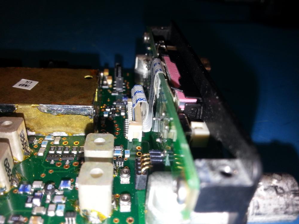
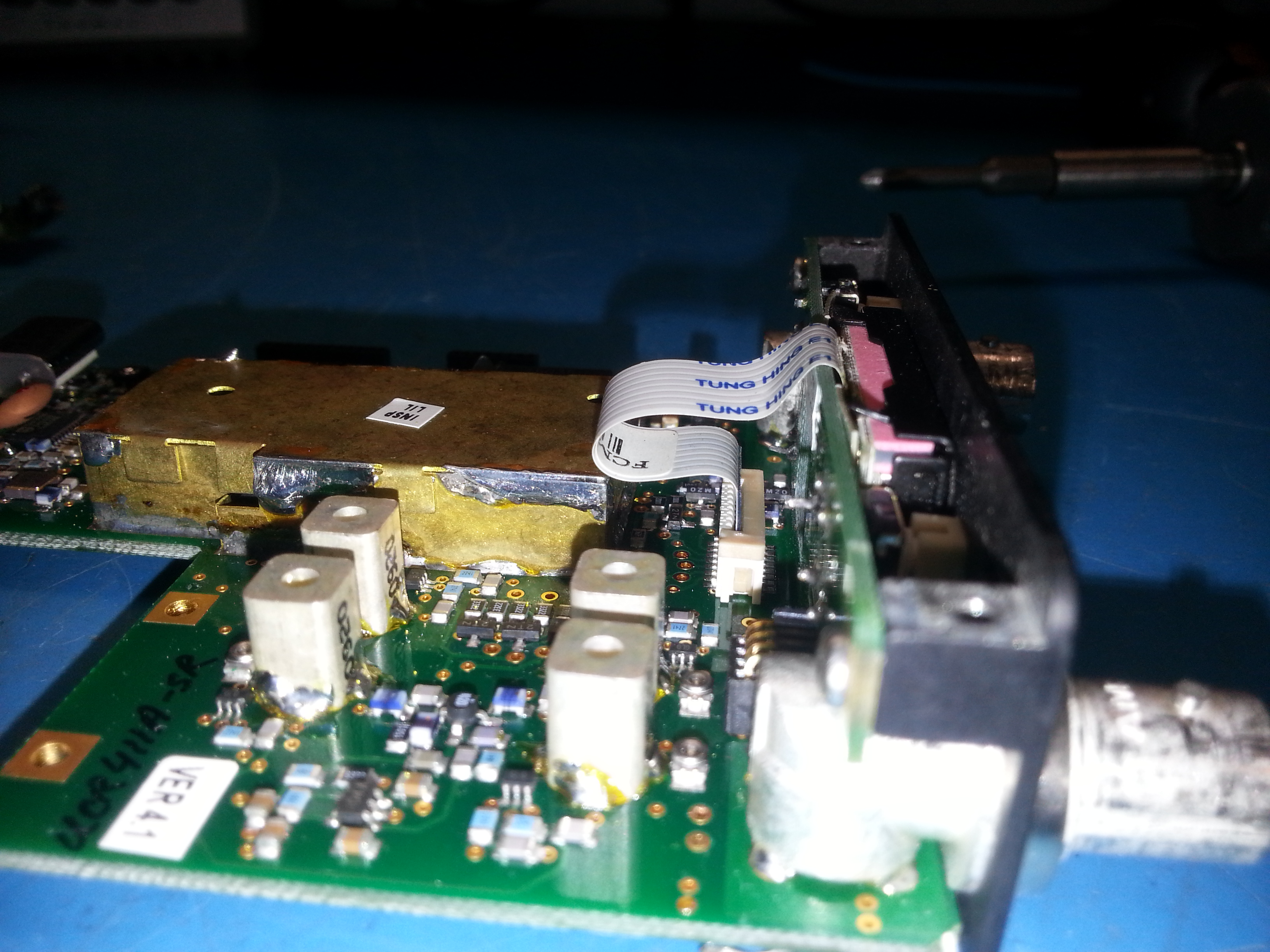
We have heard this occasionally when signals from the display (or button presses) find there way into the oscillator and "modulate" the first conversion oscillator. If your display cable is routed near the oscillator cover (1st photograph) try routing as shown in the second photograph shown here. Follow the tutorial shown on our website (up to step 7) to get access to the display cable: http://www.lectrosonics.com/US/Service-Bulletins/sb1005-lcd-display-module-pn-48353-replacement-instructions-for-ucr-series.html